The Crossbone is designed to allow the user to padhack an Xbox One first party controller with ease, eliminating >90% of the soldering and work and replacing it with a near plug and play experience.
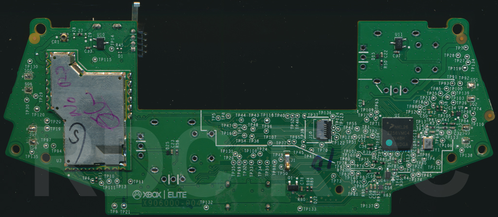
- Xbox One Controller Parts Diagram | Webmotor.org
- XB1 Controller PCB Scans, Traces And Info - 1708 'Slim'
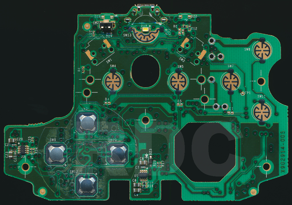
- Xbox One Controller Wiring Diagram
- See All Results For This Question
- The Xbox One controller is prone to thumbsticks (joysticks) coming loose. In most cases this problem can be resolved by gluing a small pole of metal-perhaps from a thumbtack-into the thumbstick itself and pushing this into the analogue controller mounted on the circuit board.
- Xbox Wireless Controller Red – Wireless – Bluetooth – Xbox One – PC – Red. Rated 0 out of 5 $ 598.00. Add to cart Add to wishlist.
- Posted in Arduino Hacks, Robots Hacks, Xbox Hacks Tagged Joystick, machine learning, robot arm, servo motor, unity, xbox controller, xbox one Xbox One X Gets Aluminum Laptop Makeover November 28.
Xbox One Controller Parts Diagram | Webmotor.org
It’s very simple, unhook the original top board of the connected PCBs, and replace it with the Crossbone. All of your normal input points are then broken out, including a micro USB connector for easy incorporation to your set up.
The connector is placed at a right angle to the PCB, this allows for minimal space usage, even with bulky connectors. There is also 0.1″ pitch solder points if you want to directly tie into the lines if it’s easier or better suited for your application.

The Crossbone is designed to allow the user to padhack an Xbox One first party controller with ease, eliminating 90% of the soldering and work and replacing it with a near plug and play experience. It’s very simple, unhook the original top board of the connected PCBs, and replace it with the Crossbone. All of your normal input points are.
The Crossbone also comes equipped with an on-board signal switcher so that 2 cables, or an external switching mechanism, are not needed. It defaults to the Xbox One, so if you don’t need it you don’t have to worry about it.


However to utilize it you simply attach the “SYS. 2” solder points to your second system of choice, and the “Switch” signal to whichever button you want to control this function. The “Invert” solder jumper swaps the selection, so that you could have whichever system you want as the primary in the chain of your particular setup. You simply solder the two pads together to activate the Inversion, see the below breakdown:
Invert = untouched
Switch signal grounded = SYS. 2
Switch signal left alone = Xbox 1
Invert = soldered
Switch signal grounded = Xbox 1
Switch signal left alone = SYS. 2
You can access the USB signals for all areas, including the ones after the signal switch if you need more advanced applications or need to debug an issue.
The Crossbone also comes equipped with a front end protection diode, meaning you can’t reverse the voltage on the main input, which should keep any accidental power swaps from destroying the board.
The board also contains spots for trigger fix resistors, in case you accidentally wreck the Hall Effect sensors while soldering the triggers, which are 2 of the 3 required solder points.
———————————————————————————————————————
———————————————————————————————————————
Installation
Step 1.
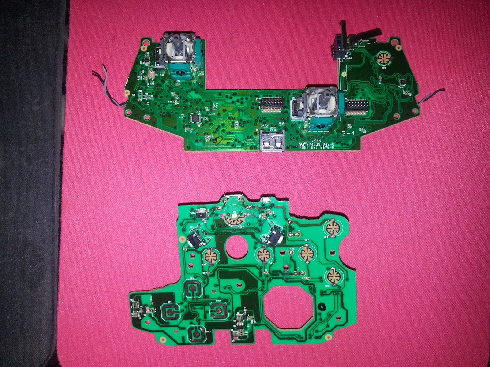
Remove the power board from the Xbox One controller PCBs, and connect the Crossbone in it’s place. Note that it makes things easy if you look in between the two boards when doing this as the Crossbone’s headers do NOT have plastic shrouding to help with alignment. This is because the headers on the Xbox One’s PCB are proprietary and no others have this matching material. Just take your time and when you have it aligned, press together.
Step 2.
Solder small wires to the required points, which are B, LT, and RT.
More details on soldering to these points can be found here:
http://forums.shoryuken.com/discussion/184953/xbox-one-padhack-thread-calling-the-goons-toodles-gummowned-phreak-and-you-do-it-for-the-kids/p1
RT and LT can be difficult for new users, and technically you can solder directly to the Hall Effect sensor’s pin, but it ensures part longevity if you solder after the resistor and capacitor pair noted in the diagrams and thread. The Crossbone does NOT have a 100 Ohm inline resistor on-board.
Step 3.
Solder the other ends to the corresponding points on the Crossbone, LT/4k IN, RT3K IN, and B/2K IN
Step 4 (set up dependent).
If your set up requires a secondary system attachment for a multi-console mod, select which input you want as your “Switch” and if you want to use “Invert” to adjust the primary system. The table is reiterated below:
Invert = untouched
Switch signal grounded = SYS. 2
Switch signal left alone = Xbox 1
Invert = soldered
Switch signal grounded = Xbox 1
Switch signal left alone = SYS. 2
———————————————————————————————————————
———————————————————————————————————————
That’s it! now you can connect the broken out points however you choose. The 3.5mm positions are easy to solder to, but will probably be offered as screw terminals as an add-on order, since not everyone wants them and they add extra height. Likewise the 20P header spot is a direct plug and play for the PS360+ PCB, but does requires that a 20P header be soldered to the PS360+ since it’s not there by default. I’m looking into ways to help avoid doing that, but soldering a 20P header is very quick work even for someone with so-so abilities.
I screwed up the triggers by pulling off the sensors!
Don’t worry, if you can still attach to the trace somewhere, the Crossbone has you covered.
Step 1. Grab a high Ohm resistor, such as a 4.7k or 10k ohm.
Step 2. Solder it into place where the “Trigger Fix” is designated. The left and right side of the board denote LT and RT, respectively.
Extra fun stuff
The Crossbone also comes equipped with circuitry to handle the LEDs, both the Home LED and IR LEDs. They are denoted in the 3.5mm screw terminal area by HO LED and IR LED, respectively. The resistors are already on-board, so the only thing you need to do is connect the anode to VCC and the cathode to the LED control point. This allows you to place the LEDs that might be beneficial to you wherever you choose, so place the Home LED externally on your stick, or route the IR LEDs to the front of it if you want to take advantage of the Xbox One’s player recognition.
XB1 Controller PCB Scans, Traces And Info - 1708 'Slim'
Fun fact, you can also connect whatever LED you want to the IR control and it will blink as it’s supposed to, which is fun but won’t actually allow the system to see/read the controller in that fashion.
FAQ
-How much?
$30
Xbox One Controller Wiring Diagram
-I still need to solder?
To take full advantage, yes. If you want to run a setup with minimal connections and deal with button mapping you can totally do that though.
See All Results For This Question
-Autodetection?
No, this thing has no brains other than to swap based on an input, this keeps costs low as the microcontroller is very inexpensive and quick to program.